Email Us

Butterfly Valves

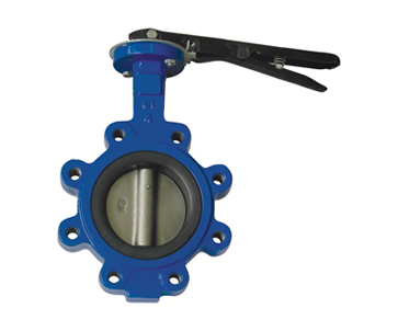
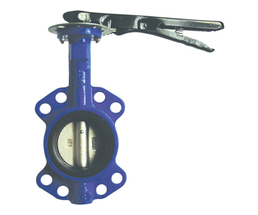
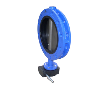
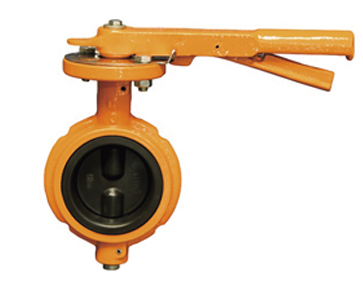
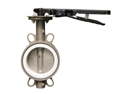
Butterfly valve has simple structure, can be used for low-pressure pipe media. It achieves the opening and closing function by turning a closing piece, names as disc, around a shaft throughout the top to the bottom of it. Butterfly valves can be used to control the flow of various types of fluids, including air, water, steam, and a variety of corrosive media, slurry, oil, liquid metals and radioactive media. It is mainly composed of valve body with a circle shape in the middle, stem/shaft, disc and seat (seal ring) built in the body.


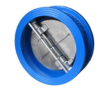
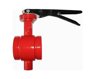
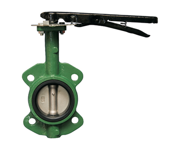
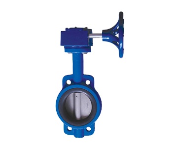
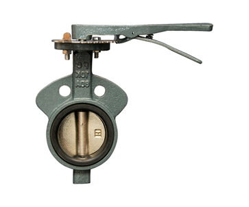
Different Types of Butterfly Valves

Butterfly Valves Dimensions and Info

Dimension11/2"-48"
End Connectionwafer type, lug type, double flanged, U-section, grooved end
Body Materialgray iron(GG25), ductile iron(GGG40/50), cast steel(WCB), stainless steel(CF8,CF8M,CF3,CF3M)
Disc Materialductile iron(nickle plated or nylon coated) caststeel(A216WCB) stainless steel(CF8,CF8M,CF3,CF3M) aluminium bronze(C954)
Seat MaterialEPDM, Buna-N(NBR),PTFE, viton, metal seated
Stem materialSS410,SS416,SS304, SS316
Actuatorhandle lever, worm gear, pheumatic actuator,chain operator
StandardAPI 609, BS5155, MSS SP-67/68, EN593


Advantages of Butterfly Valves

1. Easy to open and close quickly, labor-saving, small fluid resistance.

2. Simple structure, small form factor, short structure length, small size, light weight, suitable for large diameter valves.

3. Suitable for slurry, due to accumulate the least slurry in the valve.

4. At low pressure, it can achieve good seal.

5. Good adjustment ability.

6. Small fluid resistance at full open condition, thus high flow speed can be achieved.

7. Small opening and closing torque.

8. Good sealing performance at low pressure, because the seal material is generally rubber.

9. Easy to install.

10. Flexible operation and effort-saving, can choose manual, electric, pneumatic, hydraulic mode.

Butterfly Valves Installation

1. Install lever (for manual operated valve) or hand-wheel (for gear operated valve).

2. Using lever or hand-wheel, turn (clockwise) to ensure valve is in full closed position. Disc should be aligned parallel to the ends.

3. If disc is not aligned parallel to the ends, for lever style – slightly loosen top plate (by loosening bolts), turn lever clockwise until disc is centered & parallel to ends, and re-tighten top plate.  For gear operated valve, adjust hex nuts on side of gearbox. Fully open and close disc several times to assure proper operation. If re-alignment is necessary, repeat.

Q Butterfly Valves Installation 2
A.

4. Proceed with valve installation into the piping system. Note that "wafer: style valves are placed between flanges and installed with fully threaded studs, whereas tapped "lug" style valves are installed between flanges with small-cap screws on the inlet and the outlet of the valve.

5. Spread the mating flanges to exceed the valve's face-to-face dimension by 3/16" before placing the valve into position to prevent distortion and/or damage to the sealing face of the seat.

6. Ensure that the pipe flange faces are clean of any foreign material such as scale, metal shavings, or welding slag.

7. With the disc in the closed position, carefully insert between the flanges, line up, and center. Note that accurate centering between upstream and downstream pipe ends is essential for the trouble-free operation of the valves.


Q Butterfly Valves Installation 3
A.

8. While gradually removing the flange spreader and verifying that the valve is centered to the flanges, secure by hand-tightening flange bolts.

9. Open the valve slowly to the full open position to assure free unobstructed disc movement and that there is no contact with the piping or mating flanges. Note that disc interference may result when valves are installed in pipelines having smaller than normal inside diameters, such as heavy wall pipe, plastic-lined pipe, as-cast flanges or reducing flanges. Interference can also occur when connecting directly to a swing check or silent check. Suitable corrective measures must be taken to remove these obstructions, such as taper boring the pipe, or installing a spacer or spool piece.

10. After proper operation is verified, flange bolts should then be tightened, using a star or crisscross pattern to evenly load the bolts, to the torque values shown below in table 1.

11. Pressurize piping to valve and inspect for leakage. If leakage is observed, tighten bolts using cross-over pattern, increasing torque until leak stops. Note that recommended torques are made without warranty. Installer must verify proper strength bolts for applications. Bolts should be clean and un-lubricated.

Butterfly Valves
2 Inch Butterfly Valve
4 Inch Butterfly Valve
6 Inch Butterfly Valve
8 Inch Butterfly Valve
12 Inch Butterfly Valve
14 Inch Butterfly Valve
30 Inch Butterfly Valve


DN25 Butteryfly Valve
DN40 Butteryfly Valve
DN80 Butteryfly Valve
DN100 Butteryfly Valve
DN125 Butteryfly Valve
DN150 Butteryfly Valve
DN200 Butteryfly Valve
DN250 Butteryfly Valve
DN300 Butteryfly Valve


Butterfly Valves
Contact us